
I have seen a fair amount of discussion around “freeform” lenses on social media. A lot of it has struck me as being erroneous, so I figured it would be worthwhile to talk about it here. For most providers of optical goods, the term freeform is used to refer to progressive addition lenses (PALs) that are produced by cutting complex curves, including the progressive power surface, on the back (ocular side) of semi-finished single-vision lens blank.
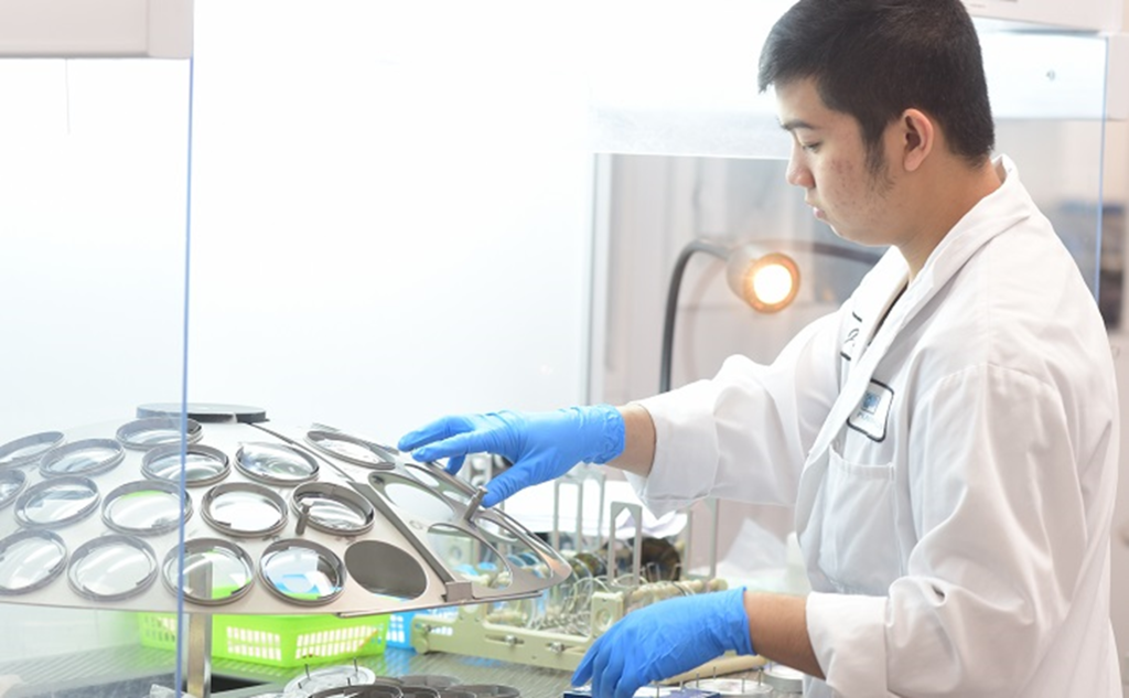
Many opticians and other practitioners have never seen the inside of a surfacing lab, so first, let’s look at how lenses have been surfaced traditionally. I’m going to give you a high-level view here, including only the major steps (so, to my fellow lab rats out there, I know I’m leaving out a few details, but I don’t think that they’re relevant to this topic).
Orders arrive at labs by several means, but these days they typically arrive into an integrated optical lab management system (LMS), such as Innovations. In addition to pricing and invoicing the order, the LMS usually figures out what blanks to use, and, if the lenses have to be surfaced, how to grind the “semi-finished” blanks to produce the thinnest possible lenses given the requirements of the order and whatever legal or conventional standards apply regarding thickness and impact resistance.
“Semi-finished” lens blanks have a finished front surface, which may be spherical (although in the distant past it was not unusual for semi-finished blanks to have toric front surfaces, which were used to produce single vision lenses in “plus-cylinder” form); they may have segments located on the front surfaces (in the case of flat-top and round seg multifocals); or they may have complex progressive-addition topologies.
Traditional Lens Surfacing: The Four Steps
In traditional lens manufacturing (also called surfacing), there are four main steps: blocking, generating, fining (also called smoothing), and polishing. Below is a brief overview of each step:
- Blocking: This consists of attaching an object to the finished front surface of the lens using one of various media (often a low-temperature melting point alloy, though more recently, multiple resins and glues have come to be used) that adhere to the block on one side and the lens on the other; the block provides a means of holding the lens in the machines.
- Generating: It cuts a spherical or toric surface on the backside of the blank. Over the years, generators migrated from using cup-style grinding tools to milling and cutting tools, which could cut more accurate toric surfaces. Still, in all cases, the surfaces produced are fairly rough, which makes the next step, called “fining” (“smoothing” in the UK), necessary.
- Fining (Smoothing): This process involves rubbing the generated surface on a “lap” (also called a “tool”) — a precisely machined metal tool shaped to the desired curves. These days, with ophthalmic lenses being almost invariably plastic, abrasive pads that adhere to the surface of the lap are sufficient to smooth the surfaces to a point at which they can be polished. A stream of water directed at the lens-lap interface removes the fine particles produced by the action of the abrasive.
- Polishing: A process virtually identical to fining (in fact, the machines are identical), except in place of the abrasive pad, a soft, porous pad is used. In place of water, a polishing compound consisting of very fine particles suspended in water is used. The pad gets saturated with the polishing compound, and that provides the action required to produce a brilliant, specular surface.
This basic four-step process for surfacing lenses remained fundamentally the same for decades. There were, however, continuous improvements in materials and techniques that made surfacing more efficient and precise.
The development of abrasive fining pads in the early 1970s was revolutionary and contributed significantly to plastic overtaking glass during that decade. Originally, a two-step fining process was necessary; the first step used an aggressive abrasive (usually silicon carbide) to not only smooth the surface but also to correct any inaccuracy in the surface (inaccuracies were common because of the use of cup-style grinding tools in the generators of the day). While some cup-style generators could produce fairly smooth surfaces (but only by running very slowly), they couldn’t produce very accurate toric surfaces. In the second fining step, a finer, softer abrasive (usually aluminium oxide) was used.
By the late 1980s, the first milling and lathe-style generators appeared in optical labs. These could directly cut surfaces with much greater form accuracy than the older grinding techniques – meaning they could produce very precise toric and complex curves. Initially, the surfaces from these CNC generators were still somewhat rough, but as the technology improved, they achieved smoother results.
In fact, as these generators evolved, they eventually became capable of producing a surface so smooth that it could go straight to polishing without any fining step at all. This capability came to be known as “cut-to-polish”. Early cut-to-polish systems still used the traditional rigid laps for the final polishing step, but the surfacing side of the business quickly recognized something game-changing: if you could directly generate polishable surfaces, you were no longer limited to simple spheres and torics. It suddenly seemed feasible to produce far more complex surface geometries – and that is when freeform began to be seen as an achievable goal.
From Cut-to-Polish to Freeform Progressives
Before cut-to-polish became possible, when people in the field saw the improvements in form accuracy and surface roughness that generators could produce, their thoughts turned to what had, until then, a kind of “Holy Grail”. What if progressive lens surfaces could be cut with these levels of surface quality, on the ocular side of spherical, semi-finished lens blanks?
– Learn how to cut lab turnaround with smarter routing, automation, and real-time visibility.
The appeal of such a capability was obvious: semi-finished single-vision blanks were (and remain) much cheaper than semi-finished progressive blanks. Furthermore, the number of different semi-finished single-vision blanks that would have to be kept in inventory (seven to twelve different base curves) would be a fraction (typically one-ninth, there being nine common add powers) of the number of different semi-finished progressive blanks that have to be kept (seven to twelve base curves times nine addition powers), if progressive surfaces of various adds could be produced on demand.
In short, freeform progressives promised significant cost savings in lens production by making each lens to order rather than drawing from an inventory of pre-moulded blanks.
Two Enablers Still Missing
Two additional innovations were required to turn these aspirations into practical realities.
Innovation #1: Polishing Complex Surfaces
The first challenge was in the polishing process. While generators could cut polishable surfaces, the existing process employed laps (also known as “tools”) cut to spherical or toric curves. The corresponding spherical or toric surfaces on the lenses to be polished could be rubbed against the lap surfaces, with a slightly abrasive polishing slurry and pad between the lens surface and the lap surface, in motions sufficiently complex and random as to avoid producing localized errors in the surfaces, which could otherwise arise from any irregularity in the lap or pad surface.
That kind of motion could not be used for a more complex surface, such as a progressive power surface. The undulations in the surface prevent the use of that rubbing motion. The solution turned out to be something quite simple: the use of “conformant” polishing laps, spun in machines that initially looked a lot like old fashioned “sphere” machines. The latter employed mushroom-shaped metal laps, spun on their “stems” (to stretch the metaphor); a lens held to the lap on one side of the lap, below its apex, would spin by virtue of the differing velocities of the spinning surface nearer to the center of the spinning lap, where the rotational velocity ultimately drops to zero, versus the outer edge.
The combination of the spinning lap surface’s curvilinear motion, the rotational spinning motion of the lens, and a third motion that moved the spinning lens across the lap surface from near the edge to near the center, produced a very efficient, randomized motion. Some of the earliest freeform polishers used that motion with a large, spherical lap, whose surface could conform to the irregular surface of the lens (hence, “conformant”). The conformant laps obtained their ability to conform to the undulating progressive surface from a layer of compressible material, not unlike a dense sponge or foam, sitting between the base of the lap and the polishing pad. This layer allowed the lap surface to conform to the irregular (that is, non-spherical, non-toric, asymmetrical) lens surface throughout the process.
Small-Aperture Laps: Better Conformance
Further refinement of this process came in the form of so-called “small-aperture” laps, which were laps having diameters smaller than the lenses – on the order of one-third to one-half the diameters of the lenses. This required that the machines become more complicated to produce the motions needed to obtain an even, randomized treatment of the lens surface. However, the smaller diameter laps conformed better to the irregular progressive surfaces than the large ones could, so the small-aperture conformant laps have become ubiquitous.
Innovation #2: Data & Communication Standards
The combination of generators capable of producing polishable surfaces, together with conformant-lap polishers made the manufacturing of complex surfaces on lenses practicable. However, an additional innovation was necessary to make the process practical. This was namely descriptions of surfaces that the generators, and to some extent, the polishers, could “understand”, to be able to produce the surfaces.
The surfaces themselves were unlike anything that had been produced commercially. Recall that the initial goal was to produce a progressive surface on the ocular (back) side of a semi-finished single vision blank. While it would have been possible to replicate a progressive design as had been produced on the object (front) side of progressive blanks on the back surface, it should be obvious that the progressive surface had to be combined with a “prescription surface” to provide usable lenses, and further, the combined surfaces would have to be adjusted to compensate for lens thickness and variations in the front surfaces of the blanks used. So, coming up with the desired surface required, and continues to require, individual calculation of the surfaces for each order.
Fortunately, early on in this process, a standard for communication between optical Lab Management Software (LMS), Lens Design Software (LDS), and freeform-capable equipment was created by extending the existing Data Communications Standard to accommodate the new data exchanges needed. The LMS could communicate with the LDS to obtain the surface design and deliver it to the machines when needed, making freeform technology commercially practical and, eventually, mainstream.